The KY-028 Digital Temperature Sensor measures temperature changes based on thermistor resistance. This module has both digital and analog outputs, there’s a potentiometer to adjust the detection threshold on the digital interface.
Compatible with Arduino, Raspberry Pi, ESP32, and other microcontrollers.
KY-028 Specifications
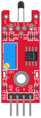
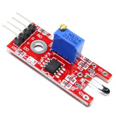
This module consists of an NTC thermistor, an LM393 dual differential comparator, a 3296W trimmer potentiometer, 6 resistors, 2 LEDs, and 4 male header pins. The module features analog and digital outputs.
| Operating Voltage | 3.3V ~ 5.5V |
| Temperature Measurement Range | -55°C to 125°C [-67°F to 257°F] |
| Measurement Accuracy | ±0.5°C |
| Board Dimensions | 15mm x 36mm [0.6in x 1.4in] |
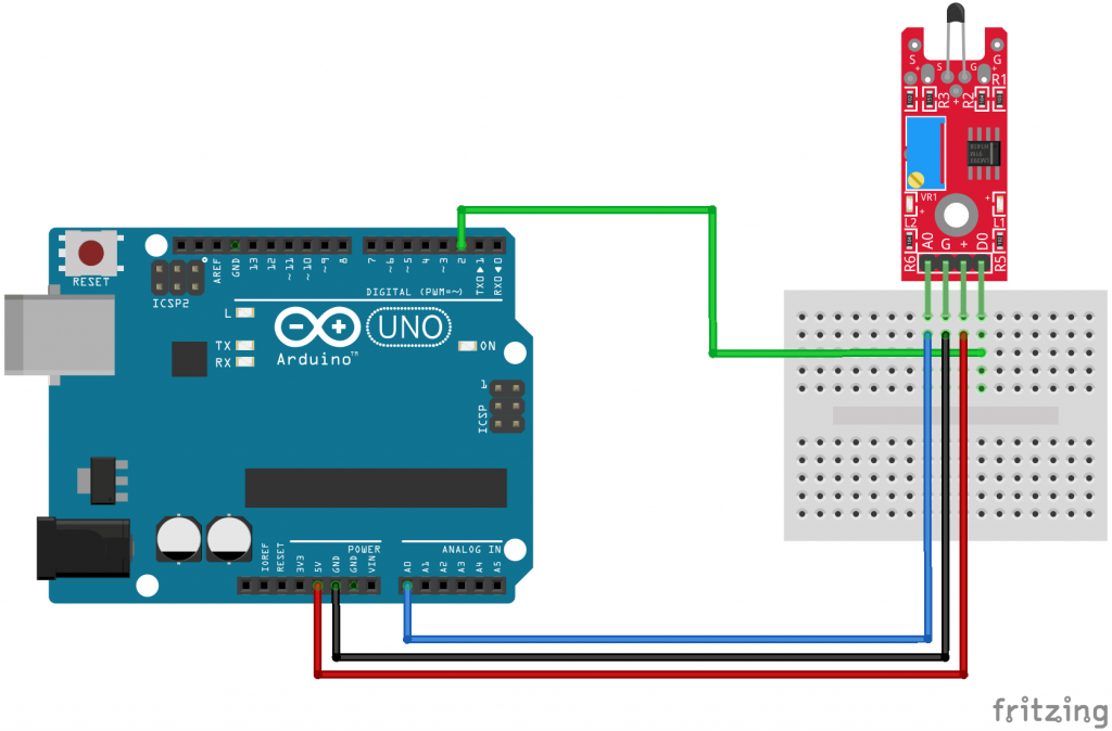
Connection Diagram
Connect the board’s analog output (A0) to pin A0 on the Arduino and the digital output (D0) to pin 3.
Connect the power line (+) and ground (G) to 5V and GND respectively.
| KY-028 | Arduino |
|---|---|
| A0 | Pin A0 |
| G | GND |
| + | +5V |
| D0 | Pin 2 |
KY-028 Arduino Code
When the temperature threshold is reached, the digital interface will send a HIGH signal turning on the LED on the Arduino (pin 13). Turn the potentiometer clockwise to increase the detection threshold and counter-clockwise to decrease it.
The analog interface returns a numeric value that depends on the temperature and the potentiometer’s position.
Since the analog output pin is directly connected to the potentiometer it isn’t possible to use the Steinhart-Hart equation to calculate the temperature as we did with the KY-013, we can only use this value to measure relative changes in temperature.
int led = 13; // define the LED pin
int digitalPin = 2; // KY-028 digital interface
int analogPin = A0; // KY-028 analog interface
int digitalVal; // digital readings
int analogVal; //analog readings

void setup()
{
  pinMode(led, OUTPUT);
  pinMode(digitalPin, INPUT);
  //pinMode(analogPin, OUTPUT);
  Serial.begin(9600);
}

void loop()
{
  // Read the digital interface
  digitalVal = digitalRead(digitalPin);
  if(digitalVal == HIGH) // if temperature threshold reached
  {
    digitalWrite(led, HIGH); // turn ON Arduino's LED
  }
  else
  {
    digitalWrite(led, LOW); // turn OFF Arduino's LED
  }

  // Read the analog interface
  analogVal = analogRead(analogPin);
  Serial.println(analogVal); // print analog value to serial

  delay(100);
}
Se puede mojar este componente
hola
Check the value of R3, on 3 PCA’s I have its a 150 Ohm (what it should be) and on 2 I have 1.5K (and very much out of range). Clearly they do not test, or someone was screwing off while testing or catching up on sleep. Found incorrect resistors on several other modules, some small and stupid like LED resistors ranging 330 to 700 Ohm’s on some boards. Some critical like 100K installed where a 10K should be.
seguiran haciendo los demas verdad?