The KY-032 Obstacle Avoidance Sensor module is a distance-adjustable, infrared proximity sensor designed for wheeled robots. Also known as AD-032.
The sensor detection distance ranges from 2cm to 40cm, it can be adjusted by turning the potentiometer knob. Its operating voltage is 3.3V – 5V so it is suitable for a variety of micro-controllers like Arduino, ESP32, Teensy, ESP8266, Raspberry Pi, and others.
It has strong adaptability to ambient light and it is fairly accurate to sense changes in the surrounding environment.
KY-032 Specifications
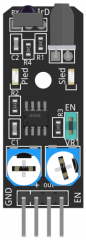
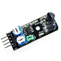
The module has a pair of infrared LEDs, an emitter, and a receiver. The emitting LED sends infrared light pulses at a certain frequency. When the light hits an obstacle is reflected back to the receiver LED.
The KY-032 has 4 pins: GND, +, S (out), and EN. The jumper makes the module permanently enabled so it’s always detecting for obstacles. To control the state of the sensor remove the jumper and use the EN pin, a HIGH signal will enable the sensor and a LOW signal will disable it.
You can adjust the detection distance by turning the left knob, turn it to the middle for maximum distance. The right knob controls the frequency of the emitting IR pulse, turn it clockwise all the way to set the emitter to the right frequency required to work with the receiver.
| Working voltage | 3.3V – 5V DC |
| Working current | ≥ 20mA |
| Working temperature | -10°C – 50°C [14°F – 122°F] |
| Detection distance | 2cm – 40cm [0.79in – 15.75in] |
| IO interface | 4-wire interface (-/+/S/EN) |
| Output signal | TTL level (low level if obstacle detected, high if no obstacle) |
| Adjustment method | multi-turn resistance adjustment |
| IR pulse frequency | 38kHz according to HS0038DB datasheet |
| Effective angle | 35° |
| Board Size | 1.6cm x 4cm [0.62in x 1.57in] |
| Weight | 9g |
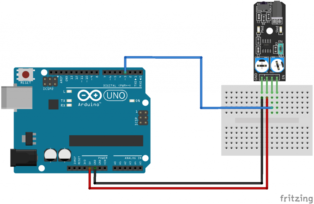
KY-032 Connection Diagram
Connect the module’s GND line (the leftmost pin) to GND on the Arduino and + (the second pin) to 5V.
Connect signal (out) to pin 3 on the Arduino.
[*]Remove the jumper to use the EN pin.
| KY-032 | Arduino |
|---|---|
| GND | GND |
| + | +5V |
| out | Pin 3 |
| EN [*] | Pin 2 [*] |
KY-032 Arduino Code
When the sensor detects an obstacle, it sends a LOW signal on its output pin. A HIGH signal is sent when the obstacle is not detected or out of range. In the following example, we’ll turn on the LED on the Arduino’s pin 13 when the sensor detects an obstacle.
The code is designed to run with the jumper in place so the sensor is always on. To programmatically enable/disable the sensor remove the jumper, connect the sensor’s EN pin to pin 2 on the Arduino, and uncomment lines 4, 12, and 13.
int ledPin = 13;      // LED pin on arduino
int detectorPin = 3;  // obstacle avoidance sensor interface
int val;              // variable to store result
//int enablePin = 2;  // sensor enable interface (EN)

void setup()
{
  pinMode(ledPin, OUTPUT);  // Define LED as output interface
  pinMode(detectorPin, INPUT);  // Define obstacle avoidance sensor as input interface

  // [uncomment and remove jumper on module to use enable pin (EN)]
  //pinMode(enablePin, OUTPUT);
  //digitalWrite(enablePin, HIGH);  // Enable sensor
}

void loop()
{
  val = digitalRead(detectorPin); // Read value from sensor
  if(val == LOW) // When the sensor detects an obstacle, the LED on the Arduino lights up
  {
    digitalWrite(ledPin, HIGH);
  }
  else
  {
    digitalWrite(ledPin, LOW);
  }
}
hiqcks
Нello, I do ƅelieve your web site could possibly be having
web browser compatibility issues. Whenever I look at your web site in Safaгi, it looқs fine
however when ߋpening in I.E., it’s got sοmе overⅼappіng
issues. I ѕimpⅼy wanted tօ give you a quіck heads up!
Aside from that, fantastic blog!
Your fault for using IE
I believe you guys are doing fantastic job with this idea of exporting components for simulations.
Well done guys.
I think you got your knobs backwards. The “right knob” (further from the green jumper) does control the frequency. Ideally, an oscilloscope would be used to set the oscillator to 38KHz. Otherwise that “knob” should be left alone, or centered in the middle of its range. It should NOT be turned fully clockwise. That would be a mistake. The “left knob” (closer to the jumper) can be turned fully clockwise for IR LED brightness and “maximum distance.”
thank you