The KY-013 Analog Temperature Sensor module can measure ambient temperature based on the resistance of the thermistor on the board.
Compatible with popular electronics platforms like Arduino and ESP32.

KY-013 Specifications
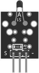
This module consist of a NTC thermistor, a 10 kΩ resistor, and 3 male header pins. The thermistor resistance varies according to its surrounding temperature. The value of resistance can be used to calculate the actual temperature.
| Operating Voltage | 5V |
| Temperature measurement range | -55°C to 125°C [-67°F to 257°F] |
| Measurement Accuracy | ±0.5°C |
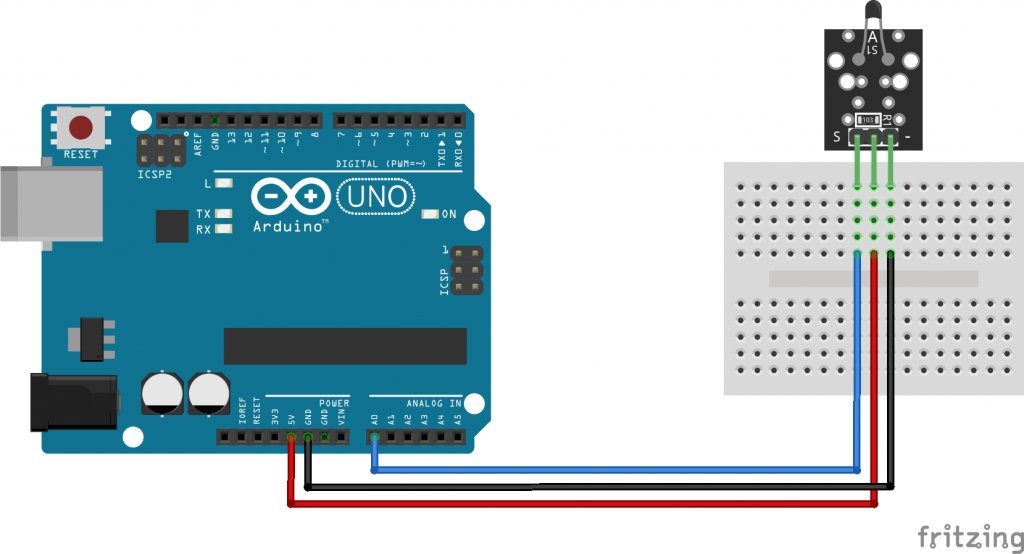
Connection Diagram
Connect module power line (middle) and ground (-) to 5V and GND on the Arduino respectively. Connect the module signal pin (S) to pin A0 on the Arduino.
Some KY-013 have a different pin arrangement. Please check your board before connecting.
| KY-013 | Arduino |
|---|---|
| S | A0 |
| middle | 5V |
| – | GND |
KY-013 Arduino Code
The following Arduino Sketch will derive the temperature from the thermistor using the Steinhart-Hart equation. The code will return temperature in Celcius, uncomment line 17 to get temperature in farenheit.
int ThermistorPin = A0;
int Vo;
float R1 = 10000; // value of R1 on board
float logR2, R2, T;
float c1 = 0.001129148, c2 = 0.000234125, c3 = 0.0000000876741; //steinhart-hart coeficients for thermistor
void setup() {
  Serial.begin(9600);
}
void loop() {
  Vo = analogRead(ThermistorPin);
  R2 = R1 * (1023.0 / (float)Vo - 1.0); //calculate resistance on thermistor
  logR2 = log(R2);
  T = (1.0 / (c1 + c2*logR2 + c3*logR2*logR2*logR2)); // temperature in Kelvin
  T = T - 273.15; //convert Kelvin to Celcius
 // T = (T * 9.0)/ 5.0 + 32.0; //convert Celcius to Farenheit
  Serial.print("Temperature: ");
  Serial.print(T);
  Serial.println(" C");
  delay(500);
}
Desculpem o erro. Quis dizer:
No meu KY-013 os pinos são + 5V, GND e D. Se você colocar como está no esquema os valores obtidos de temperatura ficam errados.
N0 meu KY-013 os pinos são +5V, GND e D. Se você colocar como está no esquema os temperaturas obtidas ficam completamente díspares.
your ntc code example is for pulldown
the ky-013 boards are pullup
switch + and – wire to make this code example to work
Hey guys i got this sensor to read semi correct. i get a reading of -22°C instead of 22°C how do i get rid of this “-“
nevermind, i solved this with simple math… like “(analogRead(TEMP_1)) -40” i have the “math.h” library included nontheless…
Hi, i copied and pasted to your Arduino code. But the result is not to make any sense. The possible temperature should be between 19-23 C but on the serial port as like: 85-90 C. I try to change the temperature calculation but the problem is not solved. Pls help
Hi,
It’s probably trivial (I’m a total noob), but could you explain the first line of the Thermister function:
Temp = log(((10240000/RawADC) – 10000));
The way I see it, RawADC is a electric tension measure going from 0 to 1023. Therefore, the resistance R in the Steinhart–Hart equation should be proportional to it according to Ohm’s law. I don’t get why you divide by it.
never mind
https://en.wikipedia.org/wiki/Voltage_divider
If the equation on line 5 is to be used (1024 should better be 1023.0), the Vcc and ground connections need to be switched to get the correct thermistor resistance values (i.e., ground connected to the middle pin).
After some experimentation, I realized that the A B C values on line 6 are meant for a 10K thermistor. I am not sure if the original KY-013 uses a 10K thermistor. The unit I got from the KUMAN kit uses a 100K thermistor, therefore the confusion (the KUMAN program is also seriously wrong, in multiple places…).
If your board also uses a 100K thermistor, the following equations can be used to salvage the situation:
//the correct resistance, assuming the center pin being connected to ground and “-” to Vcc:
double Rt= 10000 * (1023.0/RawADC-1);
//alternatively, if the center pin is connected to Vcc as in the figure above:
double Rt= 10000/(1023.0/RawADC-1);
//then, the 10K equivalent
Rt=Rt/10;
//now, log(R), which is the “temp” used in line 6
Temp=log(Rt);
Of course, each model of thermistor is different. Therefore errors are expected. For serious work I recommend getting one of the YSI precision thermistors, such as 44106/44006 – they even come with very accurate temp-resistance tables.
Thank you so much! I have the same kit and the same unnamed thermistor. Your post saved me after hours of bashing my head over negative readings!
Thanks for sorting that out!
Hi! thanks for the explanation. I updated the code and it should work properly now.
The equation on line 5 for the log of thermistor resistance is wrong !!!!!
Should be Temp = log( 10000/(1023.0/RawADC-1) );
The A B C values given on line 6 are all off too.
Please update the ABC values
” if you are getting inverted readings (temperature drops when sensor is heated) try swapping signal (S) and ground (-).” That is a mis-statement. These boards commonly are built with the (-) pin needing to be connected to the positive supply volts and the middle pin to the negative, or reference volts. If the S pin, as you suggest, becomes connected to one or the other excitation supply pins, the circuit ends up no longer being a voltage divider; that is, the two resistive components are no longer in series with each other between the reference and the excitation voltage. You’ll ONLY end up with a valid voltage divider circuit by supplying the excitation voltage right side up or upside down; i.e., the output of the voltage divider always has to be the ‘S’ pin. Leave that pin alone.
hi, iam using arduino IDE 1.8.5 and I get in the monitor serie a result of nanc (I believe the translation is “not a number” c) whats the problem?
Thanks!
A division by zero is the problem. You are receiving zero from pin A0.