The KY-037 high sensitivity sound detection module is an analog/digital sensor that uses a condenser microphone to observe changes in environment noise. Generally used to detect sound above certain levels. It has a potentiometer to set the noise detection threshold.
The digital output provides a HIGH signal when sound above the threshold is detected. The analog output shows values representing the noise levels detected by the condenser microphone, the values are relative to the provided voltage and potentiometer position, making it difficult to reconstruct the audio from the obtained values.
This module is compatible with popular microcontroller platforms like Arduino, ESP32, ESP8266, and Raspberry Pi.
KY-037 Specifications
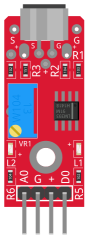
This module has a CMA-6542PF electret condenser microphone, an LM393 differential comparator to control the digital output, a 3296W potentiometer to adjust the detection threshold, 6 resistors, 2 LEDs and 4 male header pins. The module features analog and digital outputs.
| Operating voltage | 3.3V ~ 5.5V |
| Microphone sensitivity | -42 ±3 db |
| Current consumption | ~0.5mA |
| Board Dimensions | 15mm x 36mm [0.6in x 1.4in] |
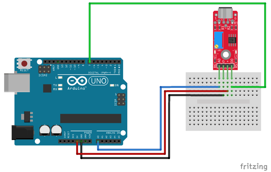
Connection Diagram
Connect the module’s analog output (A0) to pin A0 on the Arduino, and the digital output (D0) to pin 7.
Connect the module’s power pin (+) and ground (G) to 5V and GND respectively.
| KY-037 | Arduino |
|---|---|
| A0 | Pin A0 |
| G | GND |
| + | 5V |
| D0 | Pin 7 |
KY-037 Arduino Code
In the following Arduino sketch, we’ll measure the environment noise levels using the analog output of the module.
Calibrate the module’s detection threshold using the potentiometer. Turn it clockwise to increase detection sensitivity, or turn it counter-clockwise to decrease detection sensitivity.
If the module’s L2 LED is on, the noise levels are above the threshold and you should decrease the sensitivity. If the L2 LED is off, the noise level is below the threshold and you should increase the sensitivity. Turn the potentiometer to find the exact point where the LED changes its state.
Now that the detection threshold is calibrated, the digital output will activate the Arduino’s LED on Pin 13 when noise is detected. The analog output will show values relative to the supplied voltage and potentiometer position.
int digitalPin = 7; // KY-037 digital interface
int analogPin = A0; // KY-037 analog interface
int ledPin = 13; // Arduino LED pin
int digitalVal; // digital readings
int analogVal; // analog readings
void setup()
{
pinMode(digitalPin,INPUT);
pinMode(analogPin, INPUT);
pinMode(ledPin,OUTPUT);
Serial.begin(9600);
}
void loop()
{
// Read the digital inteface
digitalVal = digitalRead(digitalPin);
if(digitalVal == HIGH)
{
digitalWrite(ledPin, HIGH); // Turn ON Arduino's LED
}
else
{
digitalWrite(ledPin, LOW); // Turn OFF Arduino's LED
}
// Read analog interface
analogVal = analogRead(analogPin);
// Print analog value to serial
Serial.println(analogVal);
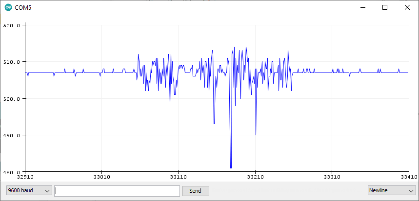
}Use Tools > Serial Plotter on the Arduino IDE to visualize the values on the analog output.