The KY-024 Linear magnetic Hall sensor reacts in the presence of a magnetic field. It has a potentiometer to adjust the sensitivity of the sensor and it provides both analog and digital outputs.
The digital output acts as a switch that will turn on/off when a magnet is near, similar to the KY-003. On the other hand, the analog output can measure the polarity and relative strength of the magnetic field.
Compatible with popular electronics platforms like Arduino, Raspberry Pi, Esp32, Teensy and others.
KY-024 Specifications
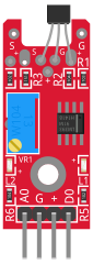
This module consists of a 49E Linear Hall-Effect Sensor, an LM393 Dual Differential Comparator, a potentiomenter, 2 LEDs, 6 resistors and 4 male header pins.
| Operating Voltage | 2.7V to 6.5V |
| Sensitivity | 1.0 mV/G min., 1.4 mV/G typ., 1.75 mV/G max. |
| Board Dimensions | 1.5cm x 3.6cm [0.6in x 1.4in] |
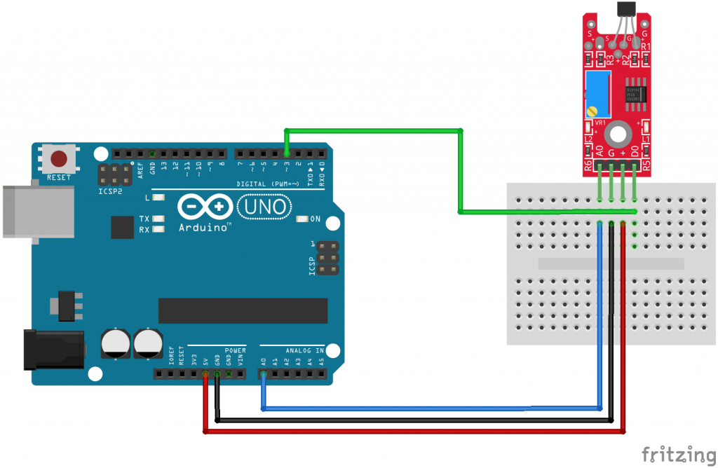
Connection Diagram
Connect board power line (+) and ground (G) to 5V and GND on the Arduino respectively.
Connect the digital signal pin (D0) to pin 3 and the analog signal pin (A0) to pin A0 on the Arduino.
| A0 | Pin A0 |
| G | GND |
| + | 5V |
| D0 | Pin 3 |
KY-024 Arduino Code
The following Arduino sketch will read values from both digital and analog interfaces on the module.
The digital interface will turn on the Arduino’s LED when a magnetic field is detected.
The analog interface starts at an initial value determined by the input voltage and the potentiometer, this value will increase or decrease depending on the intensity and polarity of the magnetic field.
int led = 13 ; // LED on arduino
int digitalPin = 3; // linear Hall magnetic sensor digital interface
int analogPin = A0; // linear Hall magnetic sensor analog interface
int digitalVal ; // digital readings
int analogVal; // analog readings

void setup ()
{
  pinMode (led, OUTPUT);
  pinMode (digitalPin, INPUT);
  //pinMode(analogPin, INPUT);
  Serial.begin(9600);
}

void loop ()
{
  // Read the digital interface
  digitalVal = digitalRead(digitalPin) ;
  if (digitalVal == HIGH) // When magnetic field is present, Arduino LED is on
  {
    digitalWrite (led, HIGH);
  }
  else
  {
    digitalWrite (led, LOW);
  }

  // Read the analog interface
  analogVal = analogRead(analogPin);
  Serial.println(analogVal); // print analog value

  delay(100);
}
Setting analog pin as input (line 11) is not necessary, the analogRead() function will automatically set the pin as analog input when used.
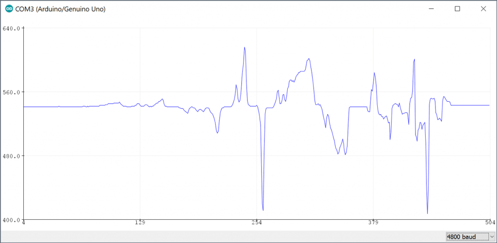
Use Tools > Serial Plotter on the Arduino IDE to visualize the changes on intensity and polarity of the magnetic field.
can I connect the KY-24 MAGNETIC HALL EFFECT SENSOR to a PLC microcontroller digital and analog input after purchasing it ?
Hi guys, any advice on how to position the sensor? Or would you recommend trial & error?
My goal is just to measure whether there is current (doorbell). Thanks!
m
Strange. My readings only go up from 531, never down no mater which way the magnet is turned!
What is the threshold for the digital setting to recognize a magnetic field is present. The analog read shows variation but the digital led is not being triggered.
Here is a detailed article for the usage of the KY 024: https://nerd-corner.com/hallsensor-ky-024-arduino-code/
It also explains the threshold.
sir what is relationship between voltage change and the corresponding distance travelled by magnet.Iam actually trying to use it for distance measurement.
hey,
in data sheet page writen: 1.0 mV/G min., 1.4 mV/G typ., 1.75 mV/G max..
here u wrote 2.5 mV/G.
what is the right one?
Hi, I took the values from a website selling the module because the original documentation in chinese is incomplete. These modules are made by several different manufacturers and sometimes the specifications are a bit different, I’m not sure if this is the case but I’ll update the values to reflect the ones on the datasheet. Thanks for pointing it out.