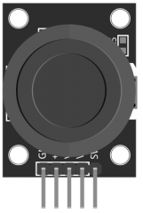
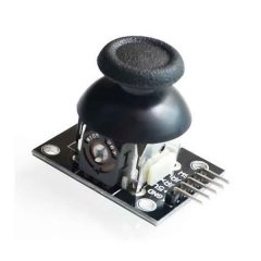
The KY-023 Dual Axis Joystick module uses a uses a biaxial potentiometer to control the X and Y axis. When pushed down, it activates a switch. Based on the PS2 controller’s joystick, it’s used to control a wide range of projects from RC vehicles to color LEDs.
Compatible with many popular electronics platforms like Arduino, Raspberry Pi, ESP32 and others.
KY-023 Specifications
This module consists of two 10kΩ potentiometers perpendicularly placed to control the X and Y axes by changing resistance when moving the joystick. A push button is activated when the joystick is pushed down on the Z axis. It has 5 male header pins.
| Operating Voltage | 3.3V to 5V |
| Board Dimensions | 2.6cm x 3.4cm [1.02in x 1.22in] |
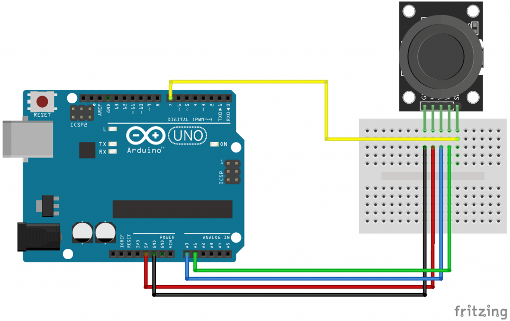
Connection Diagram
We’ll use a couple of analog pins on the Arduino to read the values from the joystick’s potentiometers and a digital pin to read values from the switch.
| KY-023 | Arduino |
|---|---|
| GND | GND |
| +5V | +5V |
| VRx | Pin A0 |
| VRy | Pin A1 |
| SW | Pin 7 |
KY-023 Arduino Code
The following Arduino sketch will continually read values from the joystick’s button and potentiometers.
Moving the joystick up/down will increase/decrease the values of X and moving the joystick left/right will increase/decrease for values of Y, these values range between 0 and 1023. Push the joystick down to activate the Z-axis button.
int value = 0;

void setup() {
	//pinMode(A0, INPUT);
	//pinMode(A1, INPUT);
  	pinMode(7, INPUT_PULLUP); //set pin 7 as an input and enable the internal pull-up resistor
	Serial.begin(9600);
}

void loop() {
  value = analogRead(A0);	// read X axis value [0..1023]
  Serial.print("X:");
  Serial.print(value, DEC);

  value = analogRead(A1);	// read Y axis value [0..1023]
  Serial.print(" | Y:");
  Serial.print(value, DEC);

  value = digitalRead(7);	// read Button state [0,1]
  Serial.print(" | Button:");
  Serial.println(value, DEC);

  delay(100);
}
Setting analog pins as input (line 4 and 5) is not really necessary, the analogRead() function will automatically set the pins A0 and A1 as analog input when called. Some people prefer to explicitly declare analog pins as input for the sake of readability.
pinMode(7, INPUT); should be pinMode(7, INPUT_PULLUP);
nicht unbedingt! Es ist auch möglich folgendes:
pinMode(7, INPUT);
digitalWrite(7, HIGH);
Das Ergebnis ist gleich