KY-019 Relay Module is used to control AC circuits, the relay acts as a switch that responds to a signal received from the Arduino, it has an integrated LED that indicates if the signal is high or low.
Commonly used in IoT projects to control lights and other electronic appliances, compatible with Arduino, Raspberry Pi, ESP32 and other microcontrollers.
KY-019 Specifications
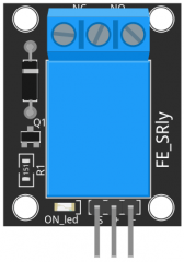
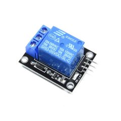
The KY-019 consist of a 1MΩ resistor, a LED, a 1N4007 rectifier diode and a 5VDC relay capable of handling up to 250VAC and 10A.
On the DC side of the board there are 3 male header pins for signal, power and ground. On the AC side there are 3 contacts, NC (Normally Closed), Common and NO (Normally Open).
| TTL Control Signal | 5VDC to 12VDC (some boards may work with 3.3) |
| Maximum AC | 10A 250VAC |
| Maximum DC | 10A 30VDC |
| Contact Type | NC and NO |
| Board Dimensions | 27mm x 34mm [1.063in x 1.338in] |
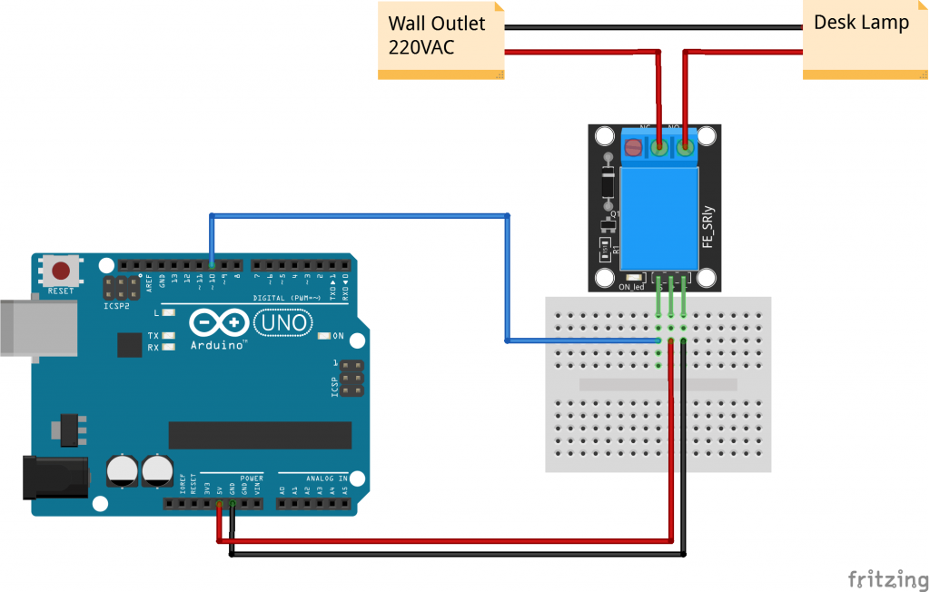
Connection Diagram
For the DC part of the circuit connect S (signal) to pin 10 on the Arduino, also connect the Power line (+) and ground (-) to +5 and GND respectively.
On the AC side connect your feed to Common (middle contact) and use NC or NO according to your needs.
NO (Normally Open) will get power when (S) is high, NC (Normally Closed) gets disconnected when (S) is high.
Always be very careful when experimenting with AC, electrical shock can result in serious injures.
| KY-019 | Arduino | AC Device |
|---|---|---|
| S | Pin 10 | |
| + | +5V | |
| – | GND | |
| NC | ||
| Common | Feed In | |
| NO | Feed Out |
KY-019 Arduino Code
The following Arduino sketch will turn the relay on/off every second. We’ll connect a desk lamp to the relay using the NO (Normally Open) connection so the lamp is off when the relay is off. Running the sketch will cause the lamp to light up intermittently.
int relay = 10;  //Pin 10

void setup()
{
	pinMode(relay,OUTPUT);  	// Define the port attribute as output
}

void loop()
{
	digitalWrite(relay,HIGH);  	// turn the relay ON
								// [NO] is connected to feed
								// [NC] is not connected to feed
	delay(1000);

	digitalWrite(relay,LOW);  	// turn the relay OFF
								// [NO] is not connected to feed
								// [NC] is connected to feed
	delay(1000);
}
WARNING
The above sketch and wireing work, but it makes you think that is ok to connect it
up to an arduino in this way.
I have got the above module and it does take 71 miliamps ( I have mesured It )
The arduinos output are 40 millamps
The arduinos output will soon burn out if it is left on , or the time is lengthend.
hola , como son los pasos para incluir este modulo en proteus ?
Hi, the .fzpz file has an issue : I’ve ordered a PCB and the GND pad has no hole on the PCB. On Fritzing forum, an expert (I’m a very beginner) said “the GND pad needs a ring pad on top of the square pad”.
Idem actually for your KY-012 fzpz file.
I hope you can generate corrected files (as I don’t know how to do that myself), because it’s really great to get those parts for fritzing.
The fixed parts are available here : https://forum.fritzing.org/t/drill-holes-sometimes-present-sometimes-missing/10944/4?u=jerome2020
Hi Jerome, sorry for the problems caused by the defective files. I’m glad to hear you’ve been able to fix it.
I uploaded the fixed parts and I will be updating the rest of the modules over the weekend. Thanks for letting me know!
I’ve 2 modules, both have the same problem: The voltage starts to swing, once the relais is switching through.
Please to supply data about current in milliamperes required for operation with 5 Volts.
Regads.
Giuliano Giuli
This is great. Thanks for creating. I have a slightly different relay and would like to modify this to match. Would you be willing to share your SVG files with me? I will do the same when done.
Hi! i’m glad you like it. You can extract the SVG file using Fritzing. Right-click on the module and select Edit (new parts editor). In the New Parts Editor window make sure the Breadboard tab is selected and click on File > Show in folder to get the SVG file.
If you’re using Inkscape to edit SVG I recommend using v0.91, the latest version (v0.92) has font size problems when used with Fritzing.
Hi, nice article, but not sure where you got your specification for the KY-019 module from, it is incorrect. The additional components are: a diode, an LED, a 150 ohm resistor (current limit for the LED) and a transistor the LED + resistor. The LED comes on when the signal is HIGH (5V).
This PDF should have the correct schematic in it:
Also, maybe the relay as a single component can be triggered by 5-12V, but it is likely that the LED would burnout with 12V with the KY-019 (?)
Hope this comment helps others who come to this page 🙂