The KY-009 RGB Full Color LED module emits a range of colors by mixing red, green, and blue light. Each color is adjusted by using PWM.
Compatible with popular electronics platforms like Arduino, Raspberry Pi and ESP32.
KY-009 Specifications
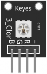
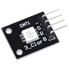
This module consists of a 5050 SMD LED and 4 male header pins. Use with limiting resistors to prevent LED burnout.
| Operating Voltage | 5V max Red 1.8V ~2.4V Green 2.8V ~ 3.6V Blue 2.8V ~ 3.6V |
| Forward Current | 20mA ~ 30mA |
| Operating Temperature | -25°C to 85°C [-13°F ~ 185°F] |
| Board Diemsions | 18.5mm x 15mm [0.728in x 0.591in] |
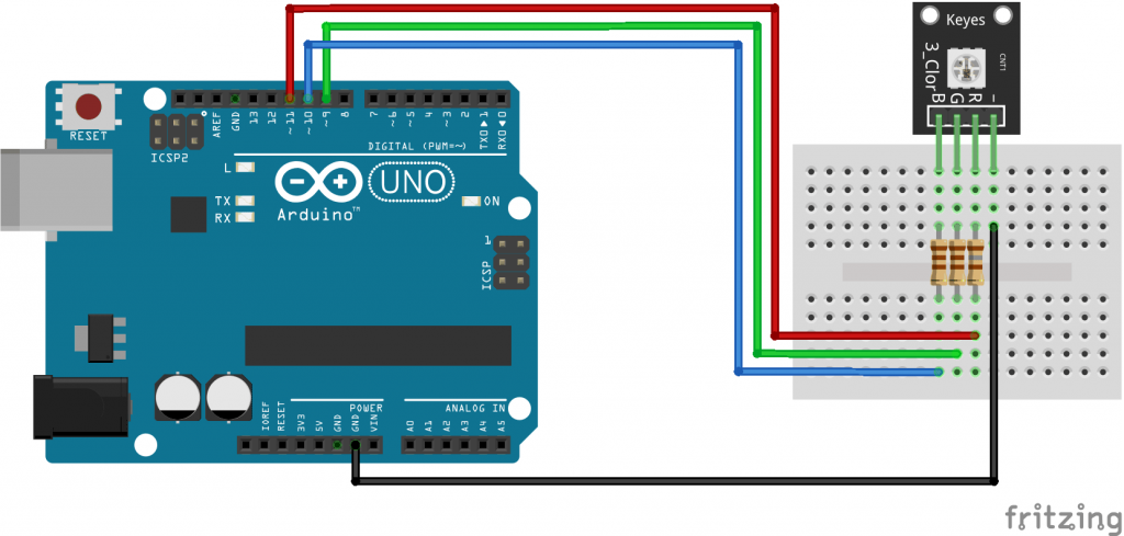
Connection Diagram
Connect the red pin (R) to Pin 9, the green pin (G) to pin 10, the blue pin (B) to pin 11 and finally the ground pin (-) to GND.
You must use resistors between the board and the Arduino to prevent LED burnout.
| KY-009 | Breadboard | Arduino |
|---|---|---|
| R | 180Ω resistor | Pin 9 |
| G | 110Ω resistor | Pin 10 |
| B | 110Ω resistor | Pin 11 |
| – | GND |
KY-009 Arduino Code
The following Arduino sketch will cycle through various colors by changing the PWM value on each of the three primary colors.
int redpin = 11; //select the pin for the red LED
int bluepin =10; // select the pin for the  blue LED
int greenpin = 9;// select the pin for the green LED

int val;

void setup() {
  pinMode(redpin, OUTPUT);
  pinMode(bluepin, OUTPUT);
  pinMode(greenpin, OUTPUT);
  Serial.begin(9600);
}

void loop()
{
  for(val = 255; val > 0; val--)
  {
    analogWrite(redpin, val);  //set PWM value for red
    analogWrite(bluepin, 255 - val); //set PWM value for blue
    analogWrite(greenpin, 128 - val); //set PWM value for green
    Serial.println(val); //print current value
    delay(1);
  }
  for(val = 0; val < 255; val++)
  {
    analogWrite(redpin, val);
    analogWrite(bluepin, 255 - val);
    analogWrite(greenpin, 128 - val);
    Serial.println(val);
    delay(1);
  }
}
Downloads
- Fritzing Part: KY-009 RGB full color LED SMD module.
- 5050 LED SMD Datasheet by Wayjun Technology.
- Fritzing Official Site.
WOW
I apologize, but better control I saw on sale there are models with the right RGB series at this point necessary to determine which module is using.
Do not consider my previous message!
I confirm.
My module has wrong pin labels, as the Green pin is the one near – pin.
So, even if pins are labeled -RGB, mine are actually -GRB.
My advice is to put at least 220Ω before each pin at first use, to determine if your pins are labeled correctly, without risking to burn the led.
HI great job, but I wanted indicate that the pins are not in the right order and not -RGB but -GRB. You can correct the component?