The KY-005 Infrared Transmitter module emits infrared light at 38kHz. It can be used to control TVs, stereos, air conditioners and other devices with IR receivers. It can also be used together with the KY-022 Infrared Receiver module.
Compatible with Arduino, Raspberry Pi, ESP32 and other popular microcontrollers.
KY-005 Specifications
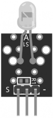
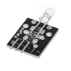
This module is quite simple and consists of a 5mm infrared LED and 3 male header pins. Handle with caution, do not flash IR light directly to the eyes.
| Operating Voltage | 5V |
| Forward Current | 30 ~ 60 mA |
| Power Consumption | 90mW |
| Operating Temperature | -25°C to 80°C [-13°F to 176°F] |
| Board Dimensions | 18.5mm x 15mm [0.728in x 0.591in] |
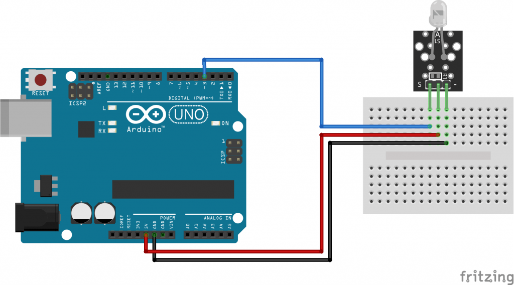
Connection Diagram
Connect the board power line (middle) and ground (-) to +5 and GND on the Arduino respectively.
Connect the signal pin (S) to pin 3 on the Arduino Uno.
The pin number for the IR transmitter is determined by IRremote library. Other platforms might use a different pin.
| KY-005 | Arduino Uno |
|---|---|
| S | Pin 3 |
| middle | +5V |
| – | GND |
KY-005 Arduino Code
The following Arduino sketch acts as a TV remote control. It uses the IRremote library to serially send instructions to a TV using infrared light.
In this example, we will send the power command for Sony TVs every 5 seconds, turning the TV on and off 10 times.
Check the IRremote library documentation for supported TV commands and devices. Links to the required libraries can be found in the Downloads section below.
You can also use the KY-022 IR Receiver module to receive and process the signal.
#include <IRremote.h>

IRsend irsend;

void setup()
{
    Serial.begin(9600); // Initialize serial interface
}

void loop()
{
    for (int i = 0; i < 10; i++) {
       irsend.sendSony(0xa90, 12); // code for Sony TV power command
       delay(5000); // wait 5 seconds
   }
}
The pinout is incorrect. The middle pin leads to smd pads and across the pads to the ground. If you’d like, you can solder an smd resistor (choose for the voltage you’ll be sending the LED) across the pads and use the center pin as gnd rather than the righthand pin. If you choose to use the rightmost pin, add an apprpriate resistor in series with the gnd pin. If you dont use a resistor on the rightmost gnd pin the magic smoke comes out. If you dont solder a resistor to the center pin pads and use the center pin as gnd, nothing happens, the circuit is open. If you connect the center pin to vcc as the pinout indicates, you’re reverse biasing the LED, it wont work, but you may warm the board a bit….
great tutorial! plugged it in and my ir led was really bright and started smoking!
fortunatly i only have to wait 35 days for the new one to arrive!
The module middle pin is actually unconnected, so it does not make sense to connect the module middle pin to 5v or anything else, for that matter.
The module led seems to work at approx. 1.1v – 20mA does not get broken when used as shown in this web page only because:
a) The Arduino (and most other microcontrollers, actually) gpio does not provide enough current.
b) The module is mostly used for remote controls, which imply the led is not ON for long enough periods of time
The middle pin could be soldered to a resistance to one of the other pins so that the led is correctly protected depending on the power source.
The module works with 1.5v, not 5v. if you connect it directly to pin 3, it will blow up, instead use a transistor. there are many guides on the internet for how to connect it properly.
Be careful – I have connected +5V to S pin and GND to – and my IR Led has blown up. This module is not secure, watch your eyes.
I do not understand the purpose of connecting the middle pin to +5V. On my device, the middle pin is only connected to an SMD pad, however, there is no resistor on the board. Thus the middle pin has no connection to the LED.
Instead I wonder, if I should connect the device directly to the Arduino output, since current should not exceed 40mA and the device exceeds this value.
I agree with thomas there is nothing connected to the middle pin except the smd pad
I know this is an old post but incase anyone else reads this, the middle pin is not in use however it is there so it can be used when you add your own resistor to the board it depends on the voltage you are using